


 English
 русский
 Español
 عربى
عربى Português
Zhongchi
Zhongchi
Zhongchi
Zhongchi
Zhongchi
Zhongchi
Zhongchi
Zhongchi
Zhongchi

Threaded Globe Valve Factory
Globe valve—The valve disc acts as the closure member. It moves along the valve seat axis to complete opening and closing operation. Globe valves are mainly used to cut off fluid. They can also regulate flow in occasions with low regulation requirements. Pay attention to installation direction. (Arrow marks are given on the valve body). Globe valves belong to forced sealing valves. Operators shall apply pressure on the valve disc while closing the valve. This can tightly prevent leakage on sealing surfaces.The sealing surface of globe valves is available in soft seal and hard seal(body integral sealing or hard alloy surfacing welding).
-
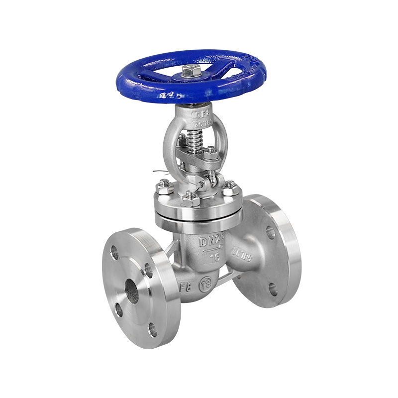

Flanged Globe Valve
-
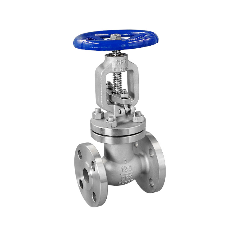
American Standard Globe Valve
-
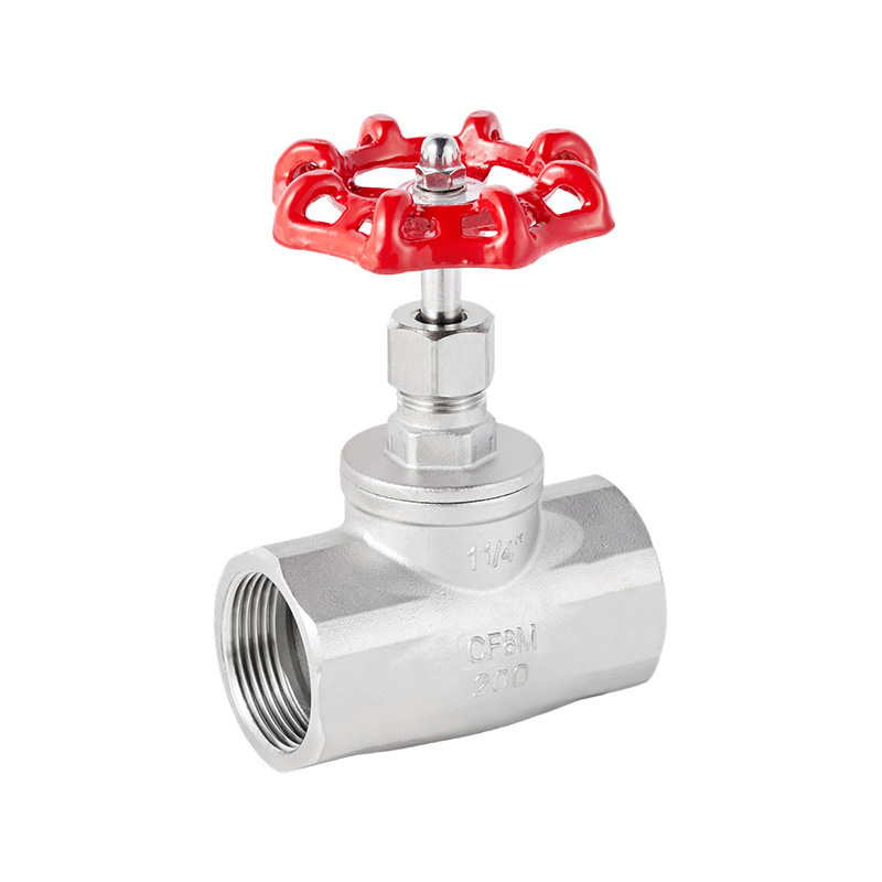
B Type Threaded Globe Valve
-
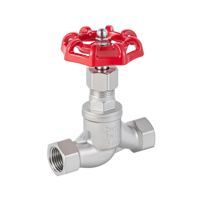
S Type Threaded Globe Valve
-
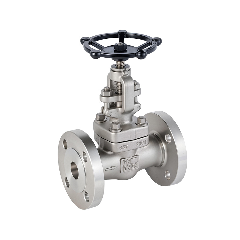
Forged Steel Globe Valve
-
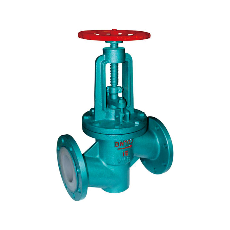
Fluorine Lined Flanged Globe Valve
About Us
Zhongchi Valve Group Co., Ltd.
Zhongchi Valve Group Co., Ltd. was established in April 2008. The company is a valve manufacturing enterprise that integrates design, development, production, and sales. It is located in the Binhai Industrial Park of Wenzhou Economic and Technological Development Zone.
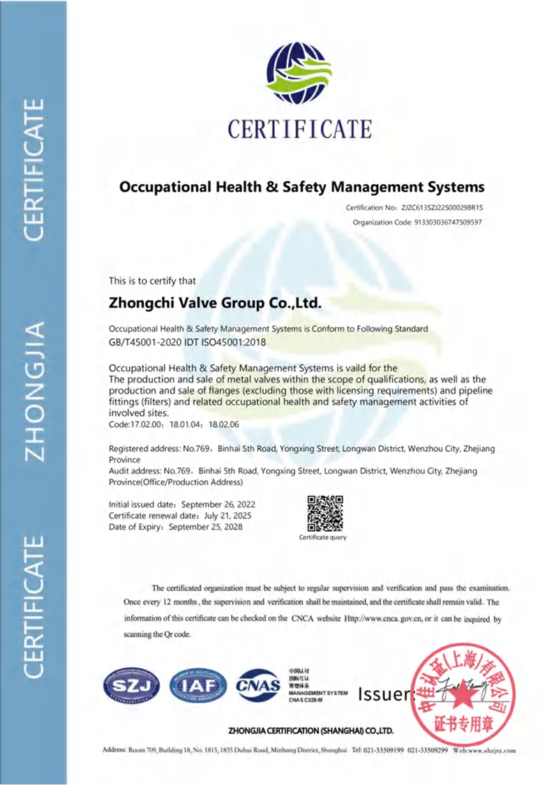
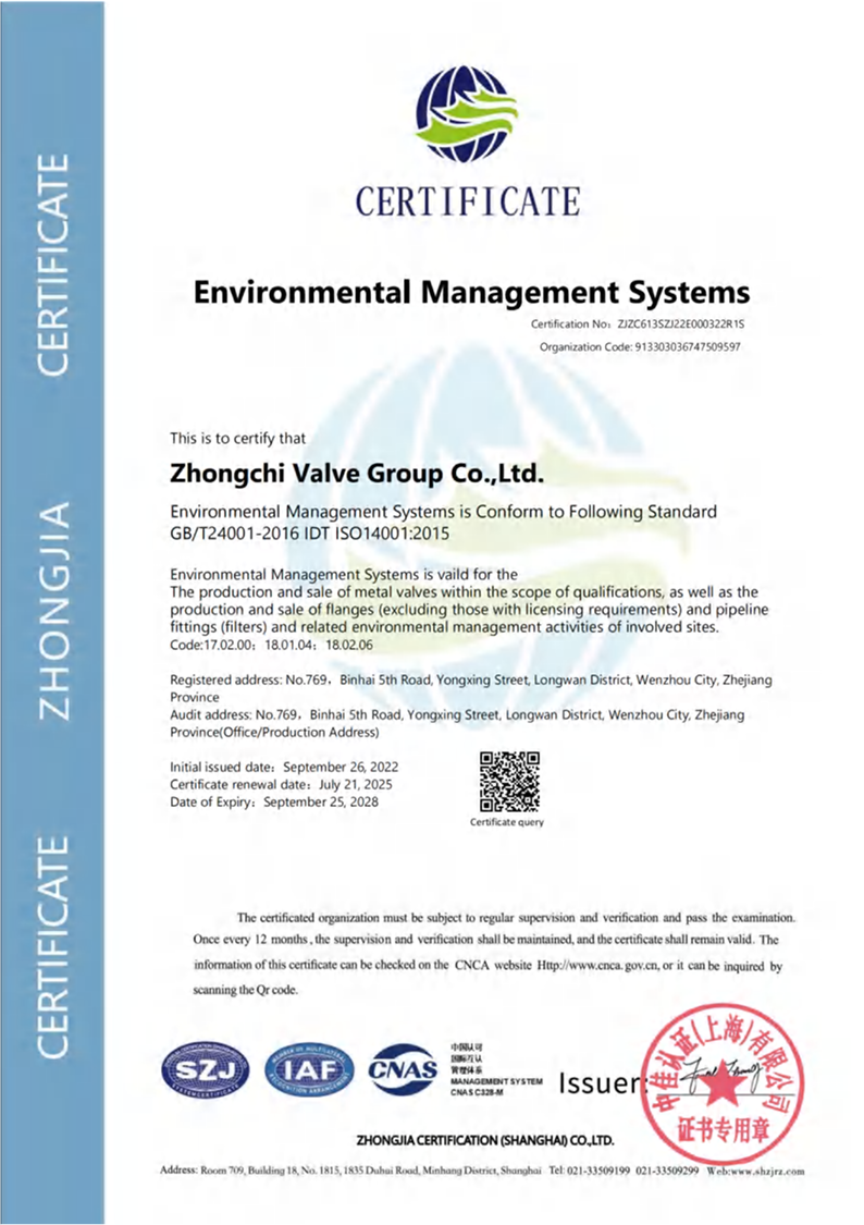
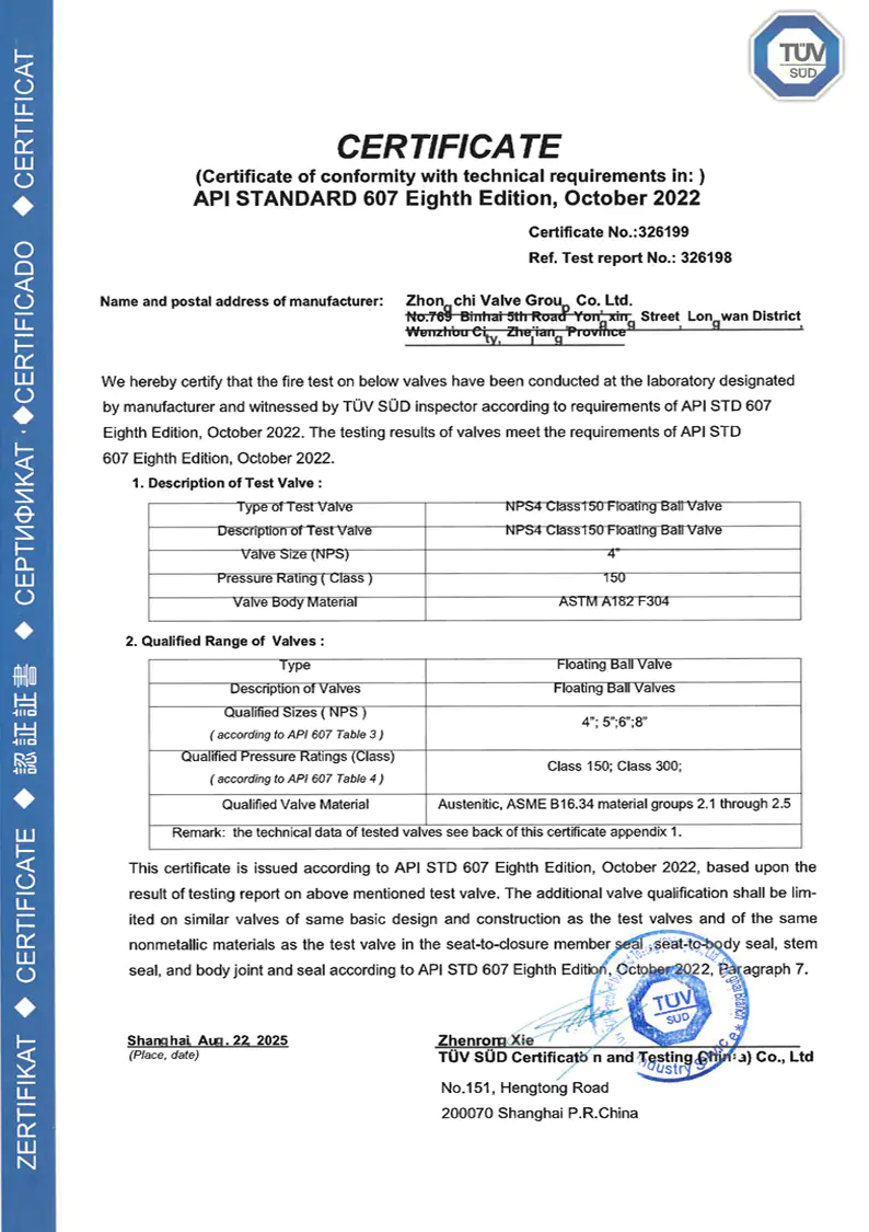
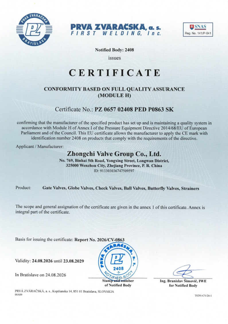
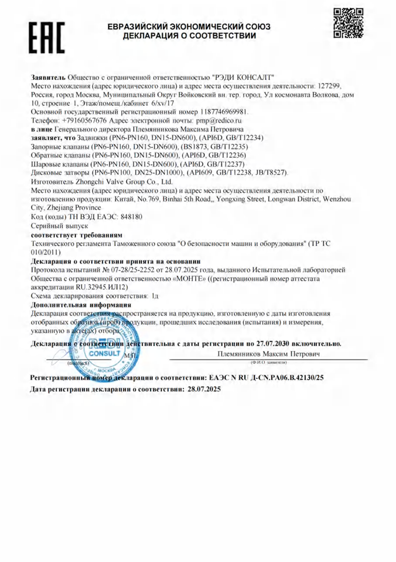
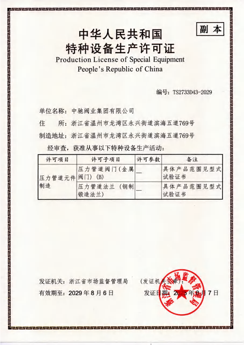
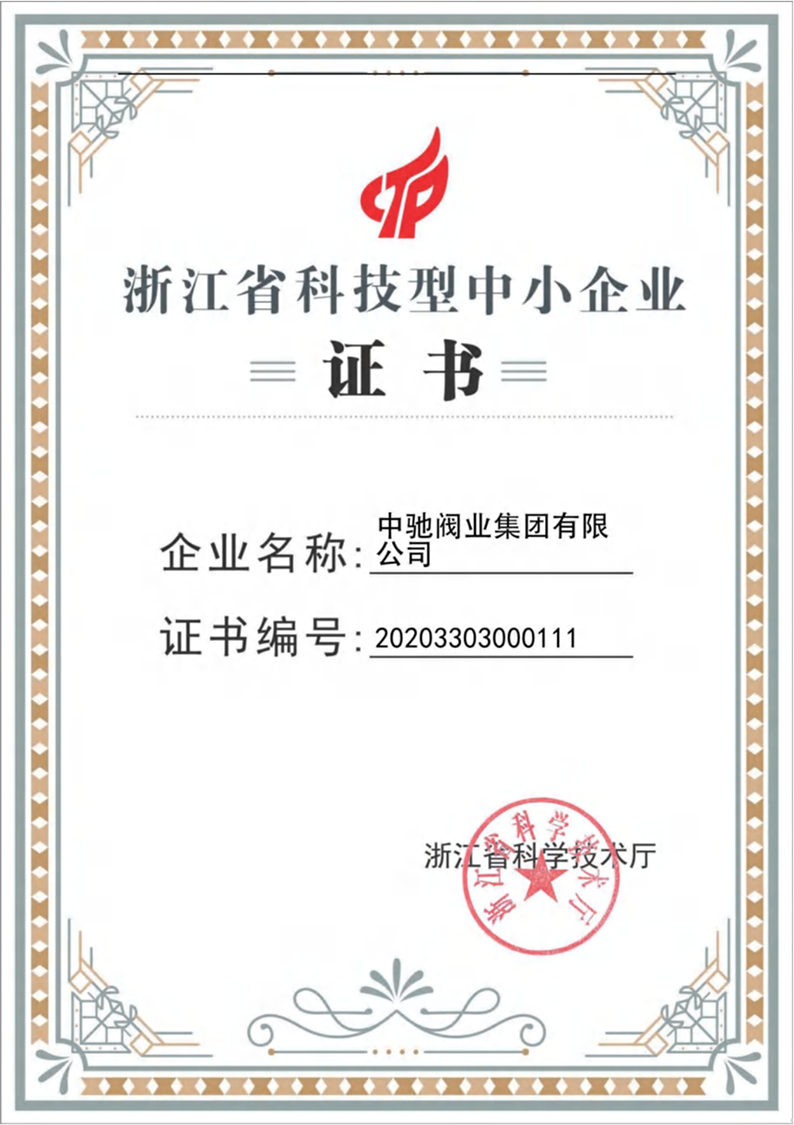
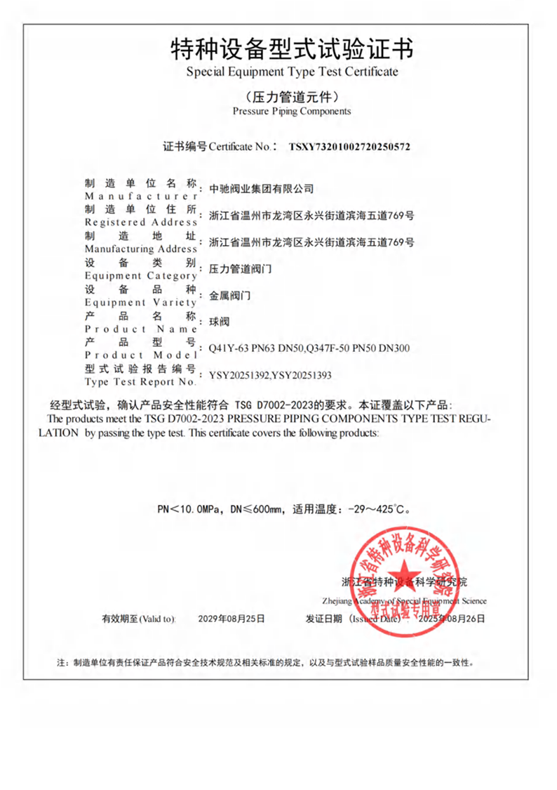
We provide customers with reliable quality assurance through advanced technology and scientific management, offers services with a complete range of products and a short delivery time, and strives to achieve the corporate goal of "building an excellent enterprise and creating a brand in the industry". The company has successively obtained ISO9001 international quality management system certification, ISO14001 environmental management system certification, ISO45001 occupational health and safety management system certification, special equipment manufacturing production license TS certification, CE certification, EAC certification, API607 fire protection certification, and has been recognized as a small and medium-sized technology enterprise in Zhejiang Province and a national high-tech enterprise.
The company's main products include ball valves, gate valves, globe valves, check valves, filters, butterfly valves, etc. These products are widely used in various industries such as petroleum, chemical, natural gas, light industry, electric power, pharmaceuticals, dyes, metallurgy, fiber, leather making, textile, food, military, construction engineering, refrigeration, water supply, and more.
We provide customers with reliable quality assurance through advanced technology and scientific management, offers services with a complete range of products and a short delivery time, and strives to achieve the corporate goal of "building an excellent enterprise and creating a brand in the industry". The company has successively obtained ISO9001 international quality management system certification, ISO14001 environmental management system certification, ISO45001 occupational health and safety management system certification, special equipment manufacturing production license TS certification, CE certification, EAC certification, API607 fire protection certification, and has been recognized as a small and medium-sized technology enterprise in Zhejiang Province and a national high-tech enterprise.
The company's main products include ball valves, gate valves, globe valves, check valves, filters, butterfly valves, etc. These products are widely used in various industries such as petroleum, chemical, natural gas, light industry, electric power, pharmaceuticals, dyes, metallurgy, fiber, leather making, textile, food, military, construction engineering, refrigeration, water supply, and more.
Stay Connected, Insights & Innovation from Zhongchi
-
 Industry News
 2026.09.25
Oil and gas valve procurement involves technical requirements that go well beyond valve size and pur...
2026.09.25
Oil and gas valve procurement involves technical requirements that go well beyond valve size and pur... -
Industry News
2026.09.25
Mesh size has an effect on what a Y‑type Flanged Strainer can retain. A finer mesh does not automati...
-
Industry News
2026.09.18
Ball valve procurement for oil, gas, chemical, and process applications involves more than choosing ...
-
Industry News
2026.09.18
Vertical piping creates a different operating condition for a check valve. Gravity affects the movem...
-
Industry News
2026.09.11
Three-way ball valves give piping systems more routing options without requiring separate valves for...
-
Industry News
2026.09.11
Global valve sourcing often involves several manufacturing regions, with China, India, and Korea ser...
Certificate Of Honor
A Practical Guide to Threaded Stainless Steel Globe Valves
Threaded stainless steel globe valves are a common sight in industrial and commercial piping systems. They're valued for their ability to provide precise flow regulation and reliable shut-off. This guide walks through their primary applications, proper installation techniques, and the fundamental mechanics of how they operate.
What Is a Stainless Steel Threaded Globe Valve Used For?
The primary purpose of a stainless steel threaded globe valve is to regulate flow in a pipeline. Unlike a gate valve, which is designed primarily for fully open or fully closed service, the globe valve excels at throttling. The wheel-style handle provides a controlled, gradual adjustment of flow.
The "globular" shape of the valve body and the internal design—where a disc moves perpendicularly onto a seat—creates a pressure drop, but this is the trade-off for its excellent control capabilities. Here's a breakdown of its common applications:
- Flow Regulation: Used where precise control of fluid flow is needed, such as in bypass lines, feedwater control, and cooling water systems.
- Chemical Handling: The choice of stainless steel (e.g., AISI 316) and PTFE seals provides excellent corrosion resistance to a wide range of chemicals.
- Food Processing: Valves with specific certifications, like compliance with CE 1935/2004, are approved for use with food products.
- Oil & Gas: Used in various applications for their durability and ability to handle moderate to high pressures (e.g., up to 32 bar for some models).
How Do You Install a Threaded Globe Valve?
Proper installation is critical to ensure a leak-free connection and long service life. The process can be broken down into a few key steps.
Preparation:
- Clean the System: Before installing, ensure all piping is blown out and thoroughly cleaned of debris, metal shavings, and sealing compound remnants. This prevents damage to the internal valve components.
- Inspect the Valve: Check the valve for any physical damage that may have occurred during shipping.
- Check Threads: Clean the male pipe threads with a wire brush. If they are damaged, run a die over them to straighten them out. Also, clean the valve's female threads.
Installation Steps:
- Apply Sealant: Apply a compatible pipe sealing compound or tape sparingly to the male pipe threads only. Crucially, do not apply sealant to the first two lead threads, as these are innermost and could push debris into the valve itself.
- Check the Flow Arrow: Position the valve so the flow arrow on the body matches the intended flow direction. This orientation also ensures that when the valve is closed, the packing is isolated from the media, making maintenance safer and easier.
- Hand Thread: Start by threading the valve onto the pipe by hand to ensure the threads mate correctly.
- Tighten with Two Wrenches: This is a critical step. Always use two wrenches: one to hold the valve body and the other to tighten the pipe fitting. Never rely on the valve itself to provide leverage, as this can twist or damage it.
- Avoid Over-Tightening: Tighten the connection, but do not over-tighten. Excessive torque can distort the valve body or damage the threads.
Post-Installation:
- Leak Test: Follow all local and national codes to pressure-test and leak-check the installation before system startup.
How Does a Screwed Globe Valve Work?
The operating principle of a globe valve is straightforward but effective.
The Mechanism:
- Valve Stem and Handwheel: The valve is operated by turning a handwheel. The handwheel is connected to a threaded valve stem.
- Rotary to Linear Motion: As you turn the handwheel clockwise, the threads on the stem rotate. This rotation is converted into linear (up and down) motion.
- Lifting the Valve Disc: The stem is connected to a disc or plug at its lower end. As the stem moves up or down, it raises or lowers the disc.
- Opening and Closing: When the handwheel is turned counter-clockwise, the stem raises the disc off the seat (a raised ring in the valve body), allowing flow. Turning it clockwise lowers the disc onto the seat, creating a tight seal and stopping flow.
| Operating Step | Handwheel Direction | Disc Position | Flow Condition |
| Opening | Counter-clockwise | Disc rises off the seat | Flow is permitted |
| Closing | Clockwise | Disc is lowered onto the seat | Flow is stopped |
| Throttling | Partial turn | Disc is partially raised | Flow is reduced but not stopped |
The threaded connection in the name simply refers to how the valve is attached to the piping system, not its internal operation.
Get a Free Quote
Quick Links
Products
Contact Information
-
 +86-13396775805
-
 +86-577-86934868
-
 cn@cnchivalve.com
-
 No. 769, Binhai 5th Road, Yongxing Street, Longwan District, Wenzhou City, Zhejiang Province, China
Copyright © Zhongchi Valve Group Co., Ltd.All rights reserved.
 Industrial Pipeline Valve Manufacturer