

 English
Zhongchi
Zhongchi
Zhongchi
Zhongchi
Zhongchi
Zhongchi
Zhongchi
Zhongchi
Zhongchi
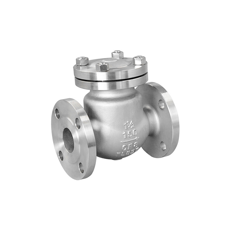
Valves are devices used in fluid systems to control the direction, pressure and flow rate of fluids; they enable the flow or stoppage of media (liquids, gases or powders) within piping and equipment, whilst also regulating their flow rate. During installation, the method used to fit valves has a direct impact on their subsequent operational performance. This article summarises some key considerations for valve installation, which we hope will be of assistance to readers.

Prohibition 1: The main materials, equipment and products used in construction lack technical quality certification documents or product conformity certificates that comply with current national or ministerial standards.
Consequences: The construction quality is substandard, posing potential safety hazards; the project cannot be delivered for use on schedule and must be reworked and repaired; this results in delays to the construction schedule and increased expenditure on labour and materials.
Measures: The main materials, equipment and products used in water supply, drainage, heating and sanitation works must be accompanied by technical quality certification documents or product conformity certificates that comply with current national or ministerial standards; they must be marked with the product name, model, specifications, national quality standard code, date of manufacture, name and location of the manufacturer, and the factory product inspection certificate or code.
Prohibition 2: Failure to carry out the necessary quality inspections on valves in accordance with regulations prior to installation.
Consequences: During system operation, valves may be difficult to open or close, fail to seal properly, or leak water (or steam), resulting in rework and repairs, and even disrupting the normal supply of water (or steam).
Measures: Before installing valves, pressure resistance and tightness tests must be carried out. Tests should be conducted on a sample of 10% of each batch (same brand, same specification, same model), with no fewer than one valve tested. For shut-off valves installed on main trunk pipes, strength and tightness tests must be carried out on each individual valve. The test pressures for valve strength and tightness must comply with the provisions of the ‘Code for Acceptance of Construction Quality of Building Water Supply, Drainage and Heating Engineering’ (GB 50242-2002).
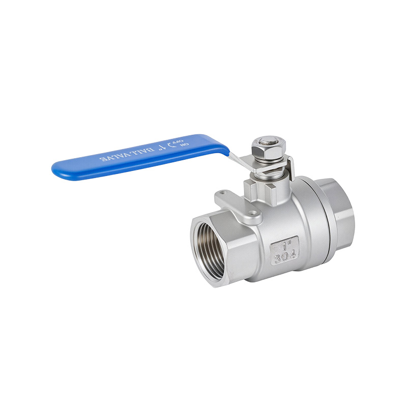
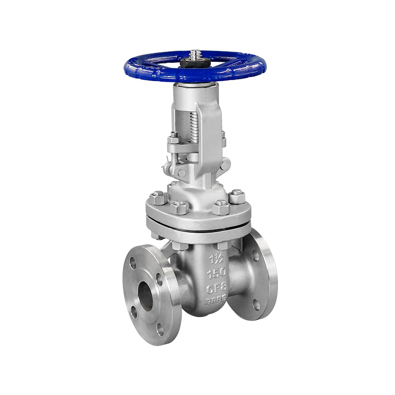
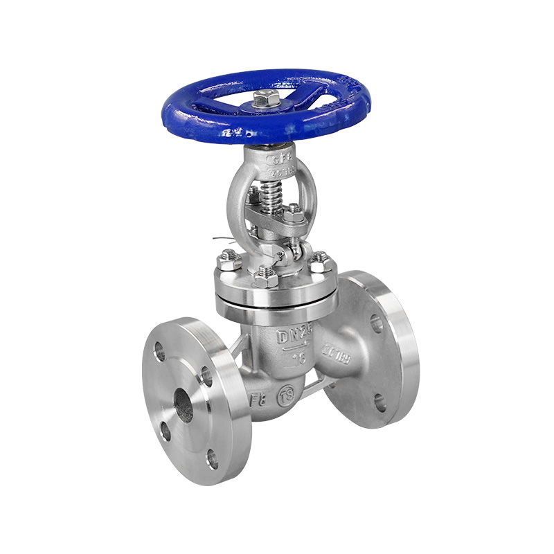
Prohibition 3: Installing valves with specifications or models that do not meet design requirements. For example: valves with a nominal pressure lower than the system test pressure; using gate valves on water supply branch pipes where the diameter is 50 mm or less; using globe valves on hot water heating mains and risers; or using butterfly valves on fire pump suction pipes.
Consequences: This affects the normal opening, closing, and regulation of resistance and pressure functions of the valves. It may even result in valve damage during system operation, necessitating repairs.
Measures: Familiarise yourself with the scope of application for various types of valves and select valve specifications and models in accordance with design requirements. The nominal pressure of the valve must meet the system test pressure requirements. In accordance with construction standards: globe valves should be used for water supply branch pipes with a diameter of 50 mm or less; gate valves should be used for pipes with a diameter greater than 50 mm. Gate valves should be used for control valves on hot water heating mains and risers, and butterfly valves should not be used on fire pump suction pipes.
Taboo 4: Incorrect valve installation methods. For example, the water (or steam) flow direction of globe valves or check valves is opposite to the markings; valve stems are installed pointing downwards; horizontally installed check valves are mounted vertically; there is insufficient space for opening or closing the handles of exposed-stem gate valves or butterfly valves; and the stems of concealed valves do not face the inspection door.
Consequences: Valve failure, difficulty in operation and maintenance, and valve stems pointing downwards often result in water leakage.
Measures: Install strictly in accordance with the valve installation manual. Ensure sufficient clearance for the stem to extend fully when opening exposed-stem gate valves, and allow ample space for handle rotation in butterfly valves. Valve stems must not be installed below the horizontal position, and certainly not pointing downwards. Concealed valves must not only be fitted with inspection hatches that allow for opening and closing, but the valve stems must also face the inspection hatch.
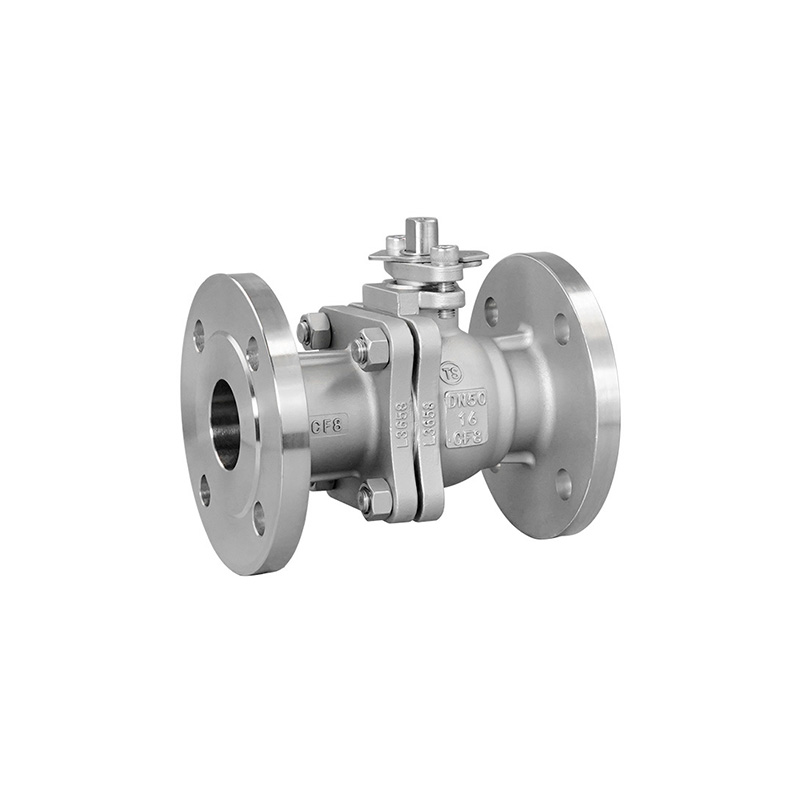
Taboo 5: Using standard valve flanges for butterfly valves.
Consequences: The dimensions of butterfly valve flanges differ from those of standard valve flanges; in some cases, the flange’s internal diameter is too small, whilst the butterfly valve disc is large, resulting in the valve failing to open or being forced open, thereby causing damage.
Measures: Flanges must be machined to the actual dimensions of the butterfly valve flange.
Taboo 6: Failure to provide reserved openings and embedded fittings during building structure construction, or providing openings that are too small and failing to mark embedded fittings.
Consequences: During the installation of heating and plumbing works, it becomes necessary to chisel into the building structure or even cut through load-bearing reinforcement, thereby compromising the structural safety of the building.
Measures: Thoroughly familiarise yourself with the heating and plumbing installation drawings. Proactively and diligently coordinate with the structural works team to ensure the provision of openings and embedded fittings in accordance with the requirements for pipe and support/hanger installation, referring specifically to design specifications and construction standards.
Taboo 7: When welding pipes, the pipe ends are not aligned on the same centreline after butt-joining; no gap is left between the ends; thick-walled pipes are not beveled; and the width and height of the weld do not meet the requirements of the construction specifications.
Consequences: Misalignment of the pipes off-centre directly affects both the quality of the weld and the visual finish. Failure to leave a gap at the joint, failure to bevel thick-walled pipes, and welds that do not meet the required width and height specifications will result in the weld failing to achieve the required strength.
Measures: After aligning pipes for welding, the pipes must not be misaligned but must be on the same centreline; a gap must be left at the joint; thick-walled pipes must have a bevel cut; furthermore, the width and height of the weld must be in accordance with specification requirements.
Taboo 8: Directly burying pipes in frozen ground or untreated loose soil; inappropriate spacing and positioning of pipe supports; or even using dry-laid brickwork.
Consequences: Due to unstable support, the pipeline may be damaged during the compaction of backfill, resulting in rework and repairs.
Measures: Pipes must not be buried in frozen ground or untreated loose soil. The spacing of supports must comply with construction specifications, and supports must be secure, particularly at pipe joints, which should not be subjected to shear forces. Brick supports must be constructed using cement mortar to ensure they are complete and robust.
Prohibition 9: Using expansion bolts of inferior quality to secure pipe supports; drilling holes that are too large for the expansion bolts; or installing expansion bolts in brick walls or even lightweight walls.
Consequences: Loose pipe supports, pipe deformation, or even detachment.
Measures: Only approved expansion bolts must be selected; where necessary, random samples should be tested. The diameter of the installation hole must not exceed the outer diameter of the expansion bolt by more than 2 mm, and expansion bolts must be used on concrete structures.
Taboo 10: Flanges and gaskets used for pipe connections are insufficiently strong; connecting bolts are too short or have an inadequate diameter. Rubber gaskets are used for hot water pipes, asbestos gaskets for cold water pipes, and double-layer or bevelled gaskets are employed, with the flange gasket protruding into the pipe.
Consequences: Flange connections are not airtight, may even be damaged, and leaks occur. A flange gasket protruding into the pipe increases flow resistance.
Measures: Flanges and gaskets used for piping must meet the requirements of the design working pressure. For heating and hot water supply pipes, rubber-asbestos gaskets are recommended; for water supply and drainage pipes, rubber gaskets are recommended. The gasket must not protrude into the pipe; its outer circumference should align with the flange bolt holes. No tapered shims or multiple gaskets shall be placed between flanges. The diameter of the bolts connecting the flanges should be 2 mm smaller than the flange bolt holes, and the length of the bolt shank protruding from the nut should be half the thickness of the nut.
Taboo 11: During hydrostatic and leak-tightness tests of the pipework system, merely observing pressure readings and water level changes is insufficient for detecting leaks.
Consequences: Leaks occur after the pipework system is put into operation, affecting normal use.
Measures: When testing the pipework system in accordance with design requirements and construction standards, in addition to recording pressure values or water level changes within the specified time, particular attention must be paid to checking for any leaks.
Prohibition 12: Concealing sewage, rainwater and condensate pipes without conducting a water-tightness test.
Consequences: This may result in water leakage, causing losses to users.
Measures: Water-tightness testing must be strictly inspected and accepted in accordance with regulations. Concealed sewage, rainwater and condensate pipes—whether buried underground, within ceilings or in pipe racks—must be ensured to be completely watertight.
Prohibition 13: Inadequate flushing of the pipework system prior to completion, with flow rates and velocities failing to meet flushing requirements. In some cases, flushing is even substituted by the drainage from hydrostatic pressure tests.
Consequences: Water quality fails to meet operational requirements for the piping system, often resulting in reduced pipe cross-sectional area or blockages.
Measures: Flushing must be carried out using the system’s maximum design flow rate or at a velocity of no less than 3 m/s. The test is deemed satisfactory only when the colour and clarity of the water at the outlet are visually consistent with those at the inlet.
Prohibition 14: Conducting hydrostatic pressure tests during winter construction at sub-zero temperatures.
Consequences: Water freezes rapidly inside the pipes during the hydrostatic test, causing the pipes to freeze and rupture.
Measures: Where possible, conduct hydrostatic tests before winter construction begins. After the test, blow the water out completely; in particular, water inside valves must be thoroughly removed, otherwise the valves will freeze and burst. If the project necessitates a hydrostatic test during winter, ensure it is carried out in a heated indoor environment, and blow the water out completely after the test. Where a hydrostatic test cannot be performed, a test using compressed air may be used.