

 English
Zhongchi
Zhongchi
Zhongchi
Zhongchi
Zhongchi
Zhongchi
Zhongchi
Zhongchi
Zhongchi
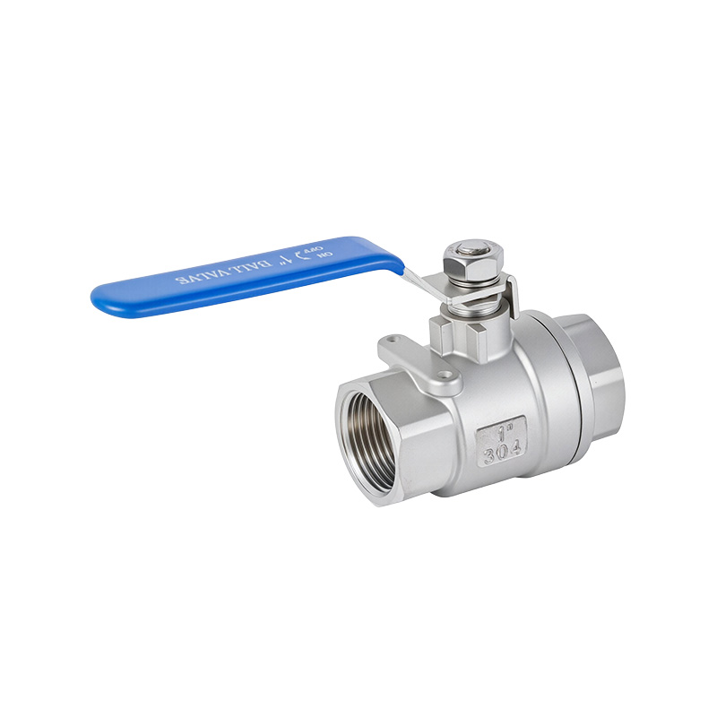
Pressure-bearing valves in the surface facilities and equipment of the Daqing Oilfield have developed internal leaks due to wear, corrosion or other causes. As internal leaks are difficult to detect, some faulty valves have not been replaced in a timely manner, which has impacted production and created safety hazards. Consequently, online valve inspection technology is attracting increasing attention; the current core technology involves the use of acoustic emission (AE) technology to detect leaks in various types of valves across industries such as petroleum, petrochemicals and power generation.
1 Basic Principles of Acoustic Emission Leak Detection
(1) Acoustic Emission Signals and Their Characterisation Parameters
Acoustic emission refers to the phenomenon whereby any metallic material or component releases strain energy in the form of elastic waves when friction, cracking or plastic deformation occurs under the action of external or internal forces. When acoustic emission waves propagate through a finite medium, they undergo refraction and reflection upon encountering interfaces, and are converted into surface waves at the solid surface, propagating along the surface at very high speeds. These acoustic emission waves originating from the source (i.e. the fault point) carry characteristic information about the source; this information can be utilised to reveal the fault and defect conditions of the component. Parameters characterising acoustic emission signals include emission rate, amplitude, amplitude distribution and energy.
(2) Characteristics of Acoustic Emission Signals in the Event of Internal Leakage in Valves
When a valve exhibits poor sealing, a small amount of fluid is constantly ejected through gaps in the valve, creating a high-speed jet. This high-speed fluid impacts the pipe wall, exciting elastic waves, i.e. acoustic emission. This constitutes a continuous-type acoustic emission signal, similar to white noise, with a frequency range of 30–50 kHz.
Characteristics of acoustic emission signals generated by valve leakage: 1. The acoustic emission waves excited by leakage are continuous; 2. The acoustic emission signals produced by leakage are relatively strong, and their amplitude is proportional to the leakage rate and to the root mean square (RMS) value of the signal.
Based on the characteristics of the acoustic emission signals generated by leakage, the characterisation parameters used are acoustic emission rate and energy; this allows for the acquisition of more comprehensive acoustic emission data, providing a more robust basis for fault identification.
2. Field Application of the Ultrasonic Detector
(1) Introduction to the Detector
When the acoustic emission waves generated by a leak reach the sensor, the sensor converts them into voltage signals which are transmitted via wires to the detector. The preamplifier amplifies the signal received from the sensor, the filter improves the signal-to-noise ratio, and the threshold circuit eliminates background noise. The microprocessor calculates, analyses and evaluates the signal. When the valve is leak-free, the display reading is 0; if there is a leak, the displayed value varies according to the severity of the leak, with higher values indicating a more significant leak. The audio components of the acoustic emission signal generated by the leak are processed and sent to the headphones, which are used to listen for the sound of the leak. When the valve is leaking, sounds of varying intensity can be heard through the headphones, and the severity of the leak can be determined based on the intensity of the sound heard.
(2) Valve Tightness Testing
When inspecting high-pressure valve systems with an ultrasonic tester, comparative readings are typically used to determine whether a leak is present: First, place the probe on the upstream side, reduce the sensitivity, and minimise other sounds; second, place the probe on the valve seat and downstream side; third, compare the differences in sound intensity. If the valve is leaking, the acoustic intensity at the valve seat or downstream side will be equal to or greater than that on the upstream side.
When inspecting low-noise systems, place the probe on the downstream side of the valve and use frequency-selective mode until the sound of fluid flow is clearly audible; then determine the presence and nature of any leakage based on the reading.
When using the four-point comparison method to detect downstream interference, such interference can sometimes be significant and propagate into the area under inspection, leading to false indications of valve leakage. The four-point method involves selecting two equidistant points, A and B, upstream, and two equidistant points, C and D, downstream. Compare the signal intensity at points A and B with that at points C and D. If point C is higher than points A and B, this indicates a valve leak; if point D is higher than point C, this indicates that the sound is being transmitted from another point downstream.
When gas or liquid leaks within a pipeline, ultrasonic waves are generated due to friction. SONAPHONEE can receive these ultrasonic signals, convert them into electrical signals and display them on the screen. At the same time, it processes the acoustic emission signals into audible sound transmitted to the headset, and can also transmit them to a PC via an infrared interface.
3. Conclusion
(1) The application of acoustic emission technology to conduct tightness testing on valves (such as water-mixing valves and bypass valves in gas valve assemblies) ensures safe production and the accuracy of energy consumption control.
(2) Testing valves replaced during the refurbishment of older facilities provides a basis for project approval decisions and reduces refurbishment costs.
(3) Ultrasonic testing technology enables online valve inspection, offering simple operation, rapid dynamic response and intuitive data. Currently, this testing equipment can only qualitatively determine whether a leak exists within the valve.